Monday, 26 May 2014

My Experience

Wow, has this class been a whirlwind or what. This assignment has at times been incredibly frustrating and stressful especially during the model generation. Even so I still have thoroughly enjoyed myself and not just because i got to create something Harry Potter based. I did not expect my final model to end up looking the way its does. In the beginning I was adamant that I was going to mostly laser cut and made from plywood. I realise now that that was quite narrow-minded. 

My conceptual MP3 player has gone through many developments and iterations to get to the final product. The things I have learnt through this process both good and bad and helpful and difficult shall be useful knowledge for future work.

Each week there has been a development in my design due to either a failure of the previous model, such as my first base sphere getting the LED stuck in the battery slot, which has had to be rethought and altered to generate a more effective solution, or a suddenly more brilliant idea that would enhance my design and make it better, such as the rastering of a pattern onto the surface of Deathly Hallows sign.

All in all it has been a success and I am happy with the work I have produced for this Assignment and my final conceptual MP3 player model. If I could go back do some things differently I would probably do more material exploration at the beginning to figure out all the options I had to work with. I would  also try and manage my time more wisely so I was more on top of the work and having models prepared for class each week. But as far as my designing and generating goes I can't think of anything I would do differently. I am happy with the process I followed and what I accomplished.

Final Conceptual MP3 Player

After everything that has happened, I , by some miracle, have a final conceptual MP3 Player model.

Conceptual MP3 Player
Software: Adobe Illustrator, Autodesk Inventor, Netfab, Up
Materials: Acrylic, Plastic
Digital Fabrication Tools: Laser Cutter, 3D Printer


It looks really awesome in my eyes. I am happy with its aesthetic and the way it disperses the light given off by the LED. Its a shame there was a little warping of the sphere but everything else turned out pretty good. It is a mission to get the LED to slot perfectly down onto the battery but is very rewarding when it works and the LED lights up, just like the puzzle idea that I considered along the pathway of this design.

Week 11: Physical Models

After the whoopsy on Friday let's give it another crack. I chucked my insert model onto the print with Roberts and Maggie. But no. There was a glitch I Robert's file which caused the print to off set at two stages. Unlucky for me, my print partook in the first stage.

Insert
Software: Autodesk Inventor, Netfab, UP
Materials: Plastic
Digital Fabrication Tool: 3D Printer


Deathly Hallows Sign
Software: Adobe Illustrator
Materials: Acrylic
Digital Fabrication Tools: Laser Cutter

Final cut pieces 
Joined with LED in its slot
Sphere Base
Software: Autodesk Inventor
Materials: Plastic
Digital Fabrication Tools: 3D Printer

Speaker representation holes turned out wonderfully, so happy with them, and they good as well
Circle in the middle this time as the two separate holes proved difficult to use 
Bottom of sphere. This time round I printed the model on its side to avoid the scaffolding catastrophe of last time. However the model warped so it is a little ovular now. this would have been alright but now the base insert gets stuck inside the sphere and requires force to place all the way in and to remove it. It also doesn't twist in it bayonet fitting because of this
Bayonet fitting printed well again
Sphere Base
Software: Autodesk Inventor
Materials: Plastic
Digital Fabrication Tools: 3D Printer

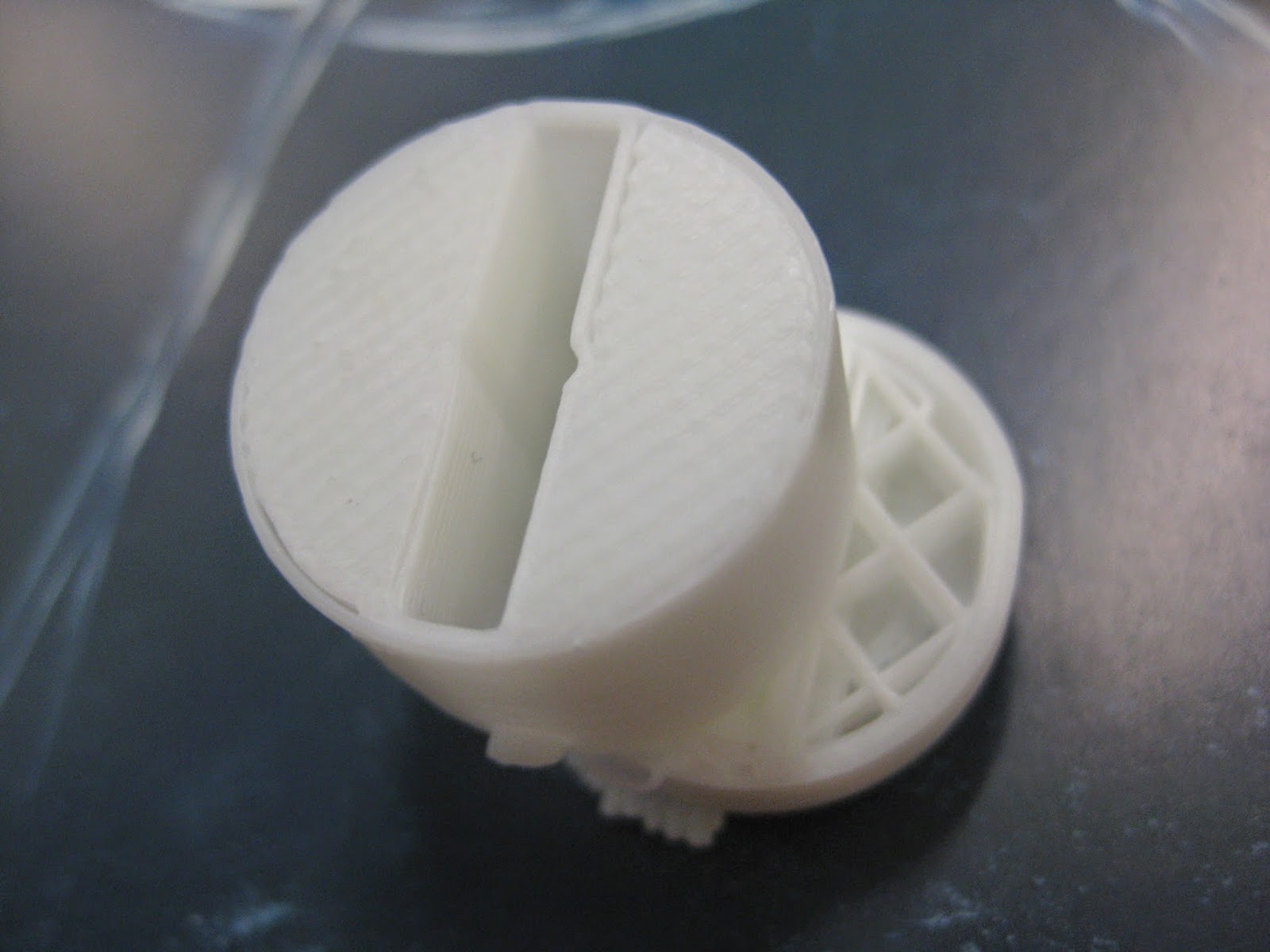
Insert finally fully printed at the right size 
pinch-able bit for placing insert in sphere and removing. Not that it works because of the warping of the sphere


Inventor is No More

Monday 26th May rocked up to the Industrial Design Building to gather the last of the screenshots I needed for my blog of my digital models in Autodesk Inventor. To continue my already wonderful day, Inventor is malfunctioning and isn't working. I hope that it would be fixed by Today, Tuesday, hand-in day I got up early to get to Uni to collect what I needed. 
Inventor still isn't working


3D Printer Whoopsy

Friday 23rd May
Micky, Sarah and I came in at 9am to print our final models for presentation on Tuesday. There was only 1/3 of the plastic we needed to print on the role that was currently on the printer. We all had a class to go to so we set up Wendy to change the roll for us. Unfortunately Wendy forgot, understandable as the Fablab was quite busy that day. 
So we only got this much of out prints printed...

Sphere base. Because of the difficulty of the scaffolding within the sphere last time I thought the results might be better if I printed this model on its side.
Base insert. This is my third print for this insert in attempt to the the measurements right for fitting into the base smoothly and not loose or tight. Luckily the printer printed got to print the little knobs on the sides so I was able to test it out in my previous sphere base to see if it works, which it did. this gave me the knowledge that I could print this again without having to worry about it fitting

Week 11: Digital Models

After learning how to accomplish what I wanted to be done, I applied it to my model. After it taking so long for me to apply this method in my tester I chose to generate speaker concept 3 instead of the golfball likeness of speaker concept 2.

Sketch mode for the second cross. Arraying the lines
All the planes I had to create just to form this concept.
Beneath all the foundation, this is what my model looks like

Knowledge Barrier

Inventor
To make the speaker representation the hole ideally would be arrayed from a single point in the centre of the sphere. 
Sadly I had no knowledge of how to do such a thing in Autodesk Inventor.
Not to late to try and learn. 
With Charlie's help we tried different ways of trying to get it done. The array tool didn't work because I'm trying to array around a sphere which has two directions where the array could only do it with one such as a cylinder.
I watched a few tutorials online to see if they would help solve the problem. The were very cool and I'm glad I now know how to use those tools, but they didn't help me solve my problem.
The next day I was in working on my model trying to find an affective way to represent my speaker that I could achieve. Charlie came in and said that I could the "tangent to a point on a curve, plane" tool. He showed me how to do it and we both thought it would work.

Tester:
I tried it out on a cylinder first before attempting to apply it to my own model.

In the sketch put a line out to every point on the sphere that you would like to create a plane on. Get the "tangent to a point on a curve tool" and create a plane at every point. Create a circle at the centre of every plane. Extrude each circle to the centre of the sphere. Yay!!

Week 11: Iterations

My speaker representation from last weeks model was a bit of a flop. It wasn't thought out well. These are my new concepts.

Line the indents with fabric to represent the speaker 
Cover the entire surface of the sphere with holes almost like a golf ball. Then it becomes a speaker all by itself 
Have the holes criss-crossed in the same fashion as the slots. still looks aesthetically pleasing
Double band of holes around the centre of the sphere. I don't particularly like this design as I think it breaks the smooth, symmetrical, fluid look of the sphere.


Week 10: Feedback

After showing my model in class today:

Speaker representation - what's the point in having a speaker on the base of my model, the sound will just play into whatever it is sitting on. Suggestions were: to convert  the entire sphere to a speaker by putting holes all over the surface, creating indents continued down from the slots and place a fabric in them.

Gazing at my model in class today I thought it looked weird with the bottom piece of the deathly hallows stopping in a straight line at the top and not continuing up to the top of the triangle. I had already had this kind of design for my first plywood model like this and I don't know why I changed it to the flat top. It is going to be changed back I think.

Week 10: Physical Models

Dealthly Hallows Sign
Software: Adobe Illustrator
Material: Acrylic
Digital Fabrication Tool: Laser Cutter

Recut. This time it has this bar for the LED to sit on.
This stops the LED from getting stuck on the battery and therefore is removed with the hallows sign so it can still act as a switch

Sphere Base
Software: Autodesk Inventor
Material: Plastic
Digital Fabrication Tool: 3D Printer

Printed in black because it was the printer available at the time. 
Printing this model hollow created a few problems. The scaffolding that was printed to supported the top of the sphere was printed quite solid. It was easy to detach from the model but because it was so thick I couldn't get it out of the model. Thus the broken off side.
The bottom of the model. The scaffolding for the top of the cylinder got stuck in there so the insert doesn't fit in its hole all the way. This means the insert doesn't use its bayonet fitting
The bayonet fitting in the base of the sphere. It printed really well to my surprise, considering its dimensions.

Insert One
Software: Autodesk Inventor
Material: Plastic
Digital Fabrication Tool: 3D Printer

This one wouldn't fit properly, it was to wide including the knobs. It got stuck halfway in and there was no way to get it out easily. I had to use extreme force
My first speaker representation on the bottom of the insert

 Insert Two
Software: Autodesk Inventor
Material: Plastic
Digital Fabrication Tool: 3D Printer

I reduced the diameter of the cylinder and the length of the extruded pins out the sides. Doing both of these things made the insert quite loose and floppy, so it rattled when connected with the sphere. But the bayonet fitting still worked and kept the insert in there
On the bottom I put a little piece to pinch which enables you to twist and unhook the insert with ease. It works well

Monday, 19 May 2014

Week 10: Digital Models

Sphere base iterations:
These have a separate compartment to house the battery as my previous design had a few complications.

Iteration One: Bayonet

flat bottom for stability 
The centre cylinder has to holes in the top for the prongs of the LED to slip into
Hollowed out inside. This allows more of the Hallows sign to be seen in the middle. It shall be interesting to see the lighting affect of the LED now the thickness of the printing has been reduced. 
Inside cylinder has a bayonet fitting on the inside for the battery insert to slot into
A simple push up and twist, no hook
Cylinder to be inserted into the bottom of the sphere base. Houses the battery for the circuit...

Prongs on the sides for the bayonet fitting
Battery slot in centre
Semi-circles on either side of the battery slot for the LED prongs to slide in next to the battery
Speaker representation on the bottom of the insert cylinder.

Iteration 2: Slot

It looks like a piggy nose
Slot space for plastic to slip into and cover the hole and exit 
If I extruded the slot further it goes through and out the other side of the base because it is a circular shape and I have it quite close to the bottom. 

Week 10: Iterations

Iteration 1: Two halves will twist together in some way
Iteration 2: Hollow cylinder in centre of sphere. Cylinder to be inserted into it with battery it that cylinder.
Iteration 3: Battery slot in centre of sphere. plastic strip to slot over the hole in the bottom so the battery doesn't fall out 
Connection Possibilities...

Put thread on the outside of the insert and on the inside of the sphere cylinder. Like a nut and bolt
Slotting on one piece and prongs on the other. Like a lightbulb
Like on a remote backing to encase the batteries